| Joint Astronomy Centre | |||
| Show document only |
|
UFTI and the FP
The 2 micron (K-band only) Fabry-Perot was commissioned with UFTI in late January 2000. The information presented below is an update of the characterisation data originally obtained with the FP on IRCAM3 (by Tom Geballe). Contents:
The low resolution, 50mm diameter Fabry-Perot etalon for the K
band was commissioned at UKIRT and had its first successful
observing run with IRCAM3 in March, 1995. The etalon has a spacing
of 40 microns, a Finesse of Q~25 across the K band, and a nominal
resolution with UFTI of 400 km/sec when properly aligned (R = mQ ~
750 for order m~30). The stability of the FP is very high compared
to older etalons; during nights on which it has been used with UFTI
the thermal drift has been less than one resolution element.
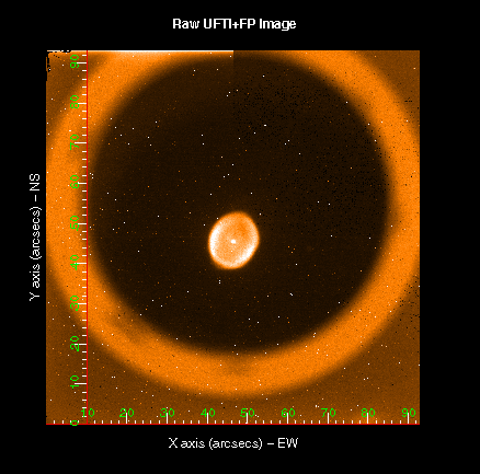
Approximately the central 70 arcsec circular diameter field of the
UFTI array, as shown below, is unvignetted.
FIG.1. A raw image of the
planetary nebula IC418 taken with UFTI through the FP tuned to Br
Gamma. These data have not been dark or sky-subtracted.
The phase shift between the centre and edge of the usable 70
arcsec field of view is ~20-30 FPZ steps - equivalent to about
70-100 km/s; between the centre pixel 512 and pixel 700 (distance 17
arcsec) the phase shift is only ~10 FPZ steps. Thus, one setting of
the FP is sufficient to accurately image an unresolved line across
the entire unvignetted field. For the same reason sky OH lines will
either be transmitted or rejected across the entire field (i.e. no
sharp rings) and will not cause serious flatfielding problems. The
separation of adjacent orders corresponds to dlambda/lambda ~0.027;
hence it is possible to use narrow band filters with percentage
bandpasses of up to about that value without transmitting an
unwanted order.
Note that because of the FP coating, it can only be used in the
K-band. However, it can be used in conjunction with IRPOL to perform
spectropolarimetry on extended line emission. The Fabry-Perot may be controlled from an ORAC sequence using an
FP iterator. A number of ORAC
reduction recipes specific to the FP now exist, and Template
Sequences are also available in the ORAC-OT Template Library.
Further details are given below.
Note that because the FP is not situated in the focal plane of
UFTI, the converging beam will result in a larger velocity
resolution than has been measured previously with IRCAM3 (with
IRCAM3 this was ~ 350 km/s). The phase shift across the array is
much shallower, however.
The following sensitivity figures have been measured for UFTI
(all data were obtained through the 2.122 micron narrow-band
filter). With UFTI's very small pixels, getting background-limited
performance from the array can be very difficult with the narrow
bandpass of the FP. Use of the "High-Gain" readout mode is therefore
recommended.
VERY IMPORTANT: MAKE SURE THAT THE CS100 HIGH VOLTAGE CONTROL
ELECTRONICS IS TURNED OFF BEFORE CABLING OR UNCABLING !!
Mounting the FP on ISU2:
Install the FP in front of UFTI. Plug in the cables from the
CS100 (they should be tied up somewhere above UFTI), being careful
that the X, Y, and Z cables are connected properly on the FP and
that the loose cable does not block part of the beam. The micrometer
settings on the FP mount should be set to:
CS100 Operation:
The CS100 is located in the lower-half of the blue electronics
rack mounted above UFTI.
Instructions for turning on and setting up the CS100 are given
below; the following steps should be followed.
Now you are ready to align the FP plates with ORAC. Instructions
on how to runup ORAC are available on KIKI and KAUWA; simply type
runup after you've logged in as observer.
Aligning the FP:
This should be done at the start of every observing run. The
Z-axis should also be checked at the beginning of each night, and
half-way through the night as the temperature changes. (Note that
the waveplate tuning is sensitive to temperature).
Alignment is achieved by finding the "tip" and "tilt" settings
(FPX, FPY) which give the maximum signal from an arc lamp line,
usually the 2.11712um line of the krypton lamp. This is found by
scanning through FPZ at different values of FPY and then FPX. NOTE
THAT IN RECENT TESTS WE FOUND IT EASIER TO ALIGN THE Y-AXIS FIRST.
The best values of FPX and FPY are determined (usually interpolated)
from these measurements. This should be done before your first night
of observing, using the ORAC FP sequences "FPY alignment" and "FPX
alignment"; these are found in the UKIRT Template Library in the
ORAC-OT. Note: you may need to arrive in Hilo a
day early so that you can align the FP with your Support Scientist
the day BEFORE your first night of observing: discuss this with your
SS!
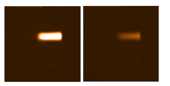
Images of the krypton lamp (through the FP perspex cover) when
the FP is fully aligned, and when not aligned, are shown below. At
present a 5 second exposure should give a few thousand counts when
aligned.
FIG.2. Images of the krypton lamp when
aligned/tuned (left) to the 2.1171 um line and when not (right).
The complete alignment procedure is available as three ORAC
Template sequences in the Template Library. The complete
procedure involves running "FPY alignment", then "FPX alignment" and
finally "FPZ alignment". Peaks in FPZ are found at different values
of FPY, then FPX (details below). With the best FPX and FPY set, a
final "FPZ alignment" sequence steps through FPZ to give the FPZ
value appropriate to the Kr line. These sequences employ the
QUICK_LOOK DR reduction recipe.
The Krypton lamp is mounted on a slider in ISU2. Position the
lamp in the beam by loosening the locking screw and sliding it into
position; its "in-the-beam" position is marked. Replace the FP
perspex cover so that only a portion of the lamp can be seen (near
the centre of the FP field of view on the array; see Fig.2 above).
Also, without the cover the lamp will be too bright.
IMPORTANT: The lamp should illuminate
the centre of the FP field-of-view, which is slightly offset from
the centre of the UFTI array, so that you tune the centre of the FP
to the correct wavelength. Moreover, the "alignfp" script used to
analyse the alignment data (described below) only measures the
signal in a box of size X=470-600 pixels, Y=580-650 pixels.
The FP alignment sequences are set to observe with the 2.122
micron H2 1-0 S(1) filter and NDSTARE (you may use the S1z filter,
but it transmits more than one line, so you must be sure to find the
stronger 2.11712 micron line). The sequences obtain series of images
at different FPX, FPY and FPZ settings; by measuring and plotting
the median average flux measured across the centre of the lamp image
at each FPX/FPY/FPZ setting, one should be able to align the three
axes so that the plates are parallel and the distance between the
plates (FPZ) is "tuned" to the wavelength of the Krypton lamp line
observed. A sequence of frames obtained with FPX and FPY fixed,
though stepping through FPZ (see below), may be analysed using a
simple script called alignfp . This shell
script examines a sequence of frames and plots to the screen the FPZ
and mean counts measured in the centre of the array (the area,
specified in pixels, should only include the central quarter of the
lamp emission/FP field of view) in each image. A plot of FPZ versus
counts is also displayed (this may be printed out).
The script uses the Kappa commands:
Running up UFTI:
In the evening the TSS will run up UFTI and datum the motors.
However, observers and support scientists will have to do this
themselves during daytime X-Y alignment.
On kiki, type dm ufti.dl & and, from the main UFTI
Epics display, open the "filter control" window (under "other
displays") and INIT the two filter wheels and the shutter. Remember,
also, to open the shutter!
Complete alignment procedure from scratch:
On Kiki: fetch and run the FPY alignment sequence (you may need
to adjust the FPZ range in the ORAC-OT).
On Kauwa: start up oracdr in the normal way; the DR will display
the raw (QUICK_LOOK) images.
Note the ampersand. In this same xterm run the alignment shell
script by simply typing
The script operates on "_raw" files in the reduced data directory
(/ukirtdata/reduced/ufti/UTdate) set by the "oracdr_ufti" command
(hence the need to run the script from the same xterm!). The script
prompts for the UT date and the start and end frame numbers of your
sequence. A plot of FPZ vs. flux is displayed by xmgr.
The ORAC-OT template sequences for FPX, FPY and FPZ alignment
obtain frames as described below (use the sequence "FPY alignment"
for steps 1-4, "FPX alignment" for steps 5-8, and "FPZ alignment"
for step 9). Note: increasing FPY by 400 moves the FPZ peak by
about -95; similarly, once FPY is fixed, increasing FPX by 700 moves
the FPZ peak by +65.
The peak in each FPZ scan usually appears
near FPZ = -700, although the peak may be considerably offset from
this value (by a few hundred FPZ steps), especially when FPX and FPY
are far from alignment. FPZ at peak signal is dependent on the
setting of the CS100 and the temperature in the dome.
Note that in all images (near alignment) the lamp should appear
as a diffuse horizontal bar across the centre of the array (see
Fig.2 above). Peak counts should not exceed 6000; if the counts are
greater than this saturation will affect your ability to reach a
sharp peak in flux across the scan.
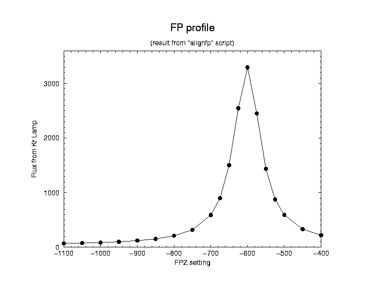
A plot of FPZ against signal should look something like the plot
in Fig.3 below. You should be able to find the peak to within 20 FPZ
steps in each case.
FIG.3. A plot of FPZ against flux measured with
the krypton lamp. The optimum values of FPX and FPY should now be entered into your
FP sequences via the ORAC-OT. The values of FPZ (the spacing between
the plates) appropriate to the 2.11712 micron krypton line observed
is temperature-sensitive. This value will need to be re-measured at
the beginning of the night and again later in the night after the
temperature has dropped. You may want to take a deep sky flat at the
beginning of the night with FPZ set to an estimated value BEFORE you
properly align FPZ. This will give time for the dome to cool down,
and the flat is probably not sensitive to FPZ.
Recent daytime tests yielded values of:
Remember that all values are affected by the settings of X, Y and
Z on the CS100.
Quick check of alignment:
The "FPZ alignment" ORAC sequence is avaliable for quick
alignment of the FPZ axis during your observing run. The sequence
takes a series of about 20 frames at different FPZ settings (in the
FPZ range of about -1000 to -250) appropriate to the 2.1171 micron
krypton line. The sequence can be found in the ORAC-OT Template
Library and used whenever the temperature changes by more than a few
degrees to recalibrate FPZ specific to the lamp line. Remember to
set FPX and FPY to your measured values in this and all other FP
sequences! The lamp (and cover) must first be installed in front
of the FP of course. Once you've obtained the sequence of frames,
run the shell script alignfp (as
described above) to get a plot of counts against FPZ setting. The
sequence could also be used to tune FPZ directly to the H2 or Br
Gamma emission line wavelengths via observations of a celestial
object (e.g. bright PN, OMC-1), although the FPZ range used by the
sequence would have to be changed.
The FWHM measured should be close to that recorded after the full
alignment procedure (see above). If the FWHM is ~110-120 steps the
FP is properly aligned. If it is much greater than 120, you will
probably need to realign the FP.
An example of the FP's lorenzian profile (i.e. counts measured
while stepping through FPZ) is shown in Fig.3 above.
At 2.1 - 2.2 micron:
Put the Krypton lamp in the UFTI beam as described above and turn
it on. With the S1 filter installed and the FPX and FPY set to their
aligned values (see above), the strong Kr 2.1171um line (vacuuum
wavelength) should be present at FPZ~-700 and FPZ~+1400. The two
orders are separated by 2116 FPZ steps. Determine the FPZ value,
FPZ(Kr2.117), for peak signal on the lamp by running the FPZ
alignment sequence described above. The following formulae then give
the correct FPZ setting for VACUUM wavelength, lambda, for your
target. (Note that you must choose a formula which gives a result in
the range -2047 < FPZ < +2047.)
This is equivalent to 0.000026752um per FPZ step.
This is equivalent to 0.000026072um per FPZ step. Note that you can use Br gamma or H2 in a bright planetary nebula
(eg NGC6572, BD+303639, NGC6572, IC2149, IC418), or H2 emission from
a Herbig-Haro object (a fainter, though pure line-emission source),
to tune or even align the FP. Some useful references for potential
targets include Kastner et al. 1996, ApJ, 462, 777 (PNe) or Davis et
al. 1997, A&A 324, 263 (HHs). Orion-OMC1 (RA=6hrs) would be
another good target for alignment purposes.
where BrG and H2 is the wavelength of Br gamma (2.166167um in
vacuum) and H2 1-0S(1) (2.121833um in vacuum) respectively. Note,
however, that the line emission will be slightly shifted due to
the PN or HH's radial velocity and the earth's motion about the
sun (20 km/s = 5 FPZ steps).
If your wavelengths are in air, the above formulae will work if
you substitute the air wavelength of the Kr line (2.11655um), the
Br gamma line (2.1655um), or the H2 line (2.1213um).
At 2.2 - 2.3 micron:
Turn on the Kr lamp and install it in front of UFTI and the FP.
With the 2-1 S(1) 2.248 micron filter installed and the FPX and FPY
set to their aligned values the bright Kr line at 2.2492um (vacuum)
should appear at about FPZ= -300 and at FPZ = +1950. The peaks are
2248 FPZ numbers apart.
This is equivalent to 0.000028220um per FPZ step.
The 400 km/sec FP drifts by about 8 steps (~ 30 km/s) per degree
Celsius. Consequently, as the night progresses and the temperature
drops, the FPZ setting for your source will need to be increased
(i.e. add 8 from FPZ for each degree C decrease in temperature) if
you are to remain tuned to the desired wavelength.
By monitoring the temperature in the dome (you may open a copy of
the TSS's weather display on KIKI by typing dm weather.dl
&), you can compensate for the drift and keep the FP set to
the correct wavelength. If the temperature changes by more than a
few degrees, however, it is advisable to retune the FPZ axis by once
again peaking up on a Krypton line or on Br gamma or H2 in a bright
planetary nebula. Note that the dome temperature is not necessarily
the same as the FP temperature!
There are a number of Template Sequences in the ORAC-OT UKIRT
Template Library; observers should copy one of these sequences to
his/her own programme and edit this to suit his/her personal
requirements. A description of how to use the OT to build up an
observing programme is given in the main
UFTI pages.
With ORAC, FP settings are treated much like spatial telescope
offsets in that an iterator must be used; the FP settings are
not set in the UFTI instrument configuration. Available template
sequences include a basic observing mode that obtains object/sky
pairs at on-line, off-line(blue), on-line and off-line(red) FPZ
wavelength settings. This sequence, "Basic(FP)", uses the ORAC-DR
recipe FP.
A similar, though considerably more involved sequence called
"Jitter 5 (FP)", obtains the same block of eight images, though with
the sequence repeated 5 times at slightly jittered positions
on-source (40 frames - plus a dark - are obtained!). This sequence
uses the FP_JITTER
recipe and can be rather time-consuming! Note, however, that fewer
than 5 jitter positions are allowed by the recipe.
Lastly, the "Jitter 5 no sky (FP)" sequence assumes that the sky
background is negligeable and so does not need subtracting; no sky
frames are obtained (and so only 20 frames - plus a dark - are
observed). This sequence uses the FP_JITTER_NO_SKY
recipe.
The choice of whether to use FP_JITTER or FP_JITTER_NO_SKY is
left to the observer, although note that for very faint sources
taking sky frames may be prudent. In raw exposures, users will
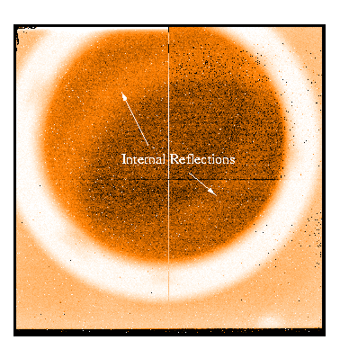
notice "reflections" in the FP field of view. These diffuse bands
are low-level and fairly stable, so in most cases they will
flat-field out. Subtracting these reflection bands out may be a
better option, however. A raw 120sec HiGain exposure of a faint
target is shown below; the reflection bands are labelled.
FIG.1. A raw 120sec exposure
of a faint galaxy; note the faint diffuse reflections. These data
have not been dark-subtracted, sky-subtracted or flat-fielded.
All FP recipes require appropriate dark exposures. A
separate, blank-sky flat-field must also be obtained. The Template
sequence "Make_Skyflat for FP" (which uses the DR recipe SKY_FLAT_FP)
may be used for the latter.
Available ORAC sequences and a description of the associated
recipes is given here.
A more comprehensive description of ORAC, the OT and QT, is
available here,
though note that this is a general description and so is not
specific to use with UFTI.
Since the filter transmission may vary at different FPZ settings,
it may be a good idea to obtain a separate flux standard mosaic at
each of the FPZ values used on the target. For example, one could
observe a 5-point jitter pattern at each of the FPZ settings; with
these separate mosaics (one per FPZ value) target frames can then be
individually calibrated before "continuum" images are subtracted
from "line" images. To obtain separate mosaics, nest the 5-point
offset iterator within the FPZ iterator in your ORAC-OT sequence.
Then reduce the data with BRIGHT_POINT_SOURCE. This will use a
pre-obtained flat (the same flat used by the FP recipes; it must be
obtained through the same NB filter) and will produce separate
mosaics named "_mos_0.sdf", "_mos_1.sdf" and "_mos_2.sdf". The
template sequence "Flux Standard for FP" in the ORAC-OT UFTI+FP
template library may be copied and edited for this purpose.
Choosing a standard can be tricky. As a rough guide, a good
signal (one to two thousand counts) should be obtained on a 7-8th
magnitude A-type standard star with UFTI and the FP in 5 seconds
integration. Note, however, that the UKIRT Faint standards are
generally too faint (10th-13th mag.) and the stars in the
Bright-star catalogue are too bright (4-6th magnitude)! Observers
should probably use a star from the Elias
"Faint" standards list (1982) or the catalogue of Maiolino,
Reike and Reike (1994); both lists are taken from the IRTF web
pages. Most of these stars are 7-8th magnitude at K - just right for
the FP!
What about Sky Flats? Getting a few hundred counts on the array
with the FP is very difficult. Even with HiGain mode, a two-minute
exposure during the night will give only a hundred counts or so;
this is barely background limited, and certainly not enough for a
"noise-free" flat-field. Observers have two options. The first is to
use much longer exposures: the "make skyflat for FP" sequence in the
Template library is set up to obtain four dithered sky frames (with
FPZ set to the same on-line, off-line(blue), on-line and
off-line(red) values as used on the target) with a 500sec
exposure time. Alternatively, it is possible to get a
good flat at Sunrise/Sunset. Recent observations indicate that a
60sec HiGain exposure within 5-10mins of sunset (with the telescope
near zenith) will give 500-1500 counts on the array. Be prepared;
the sun sets/rises very quickly, so you'll only have 20-30mins
before the opportunity has passed! Also, please be careful not to
"fry" the array - latency/persistence effects, resulting in
rectangular bias structures across the array, could hamper
subsequent observations. These
test observations should give you some idea of exactly when to
take your blank sky exposures. Remember to "flush" the array with
lots of short dark exposures after any observations that involve
high flux levels (e.g. sky flats, lamp observations [during
alignment] or standard star observations).
And lastly, remember that you must obtain sky flats before
you observe your target and/or standard star if the FP DR recipes
are to work.
|
